Live product catalog
Worm Shafts & Worm Gear Components
Browse worm shafts by manufacturing route, start count, material requirement and JDLB dual-lead series context. Product pages show the information we can confirm and clearly flag the dimensions that must come from the ordered drawing.

How to use this catalog
Use the category structure to narrow the manufacturing route or drive concept first. A product page is a quoting and selection destination, not a promise that one generic shaft fits every worm wheel.
When you already have a drawing, the fastest route is to open the closest product family and send the print through the RFQ. When you are replacing an unknown shaft, start with the replacement guide and include the mating wheel or reducer identification.
Selection checkpoints before you compare products
| Paramètre | Spécifications / guide |
|---|---|
| Géométrie | Module or diametral pitch, starts, hand, pressure angle, lead/lead angle and worm profile definition. |
| Mating part | Worm-wheel tooth count, material, center distance, contact pattern/backlash target and any existing model reference. |
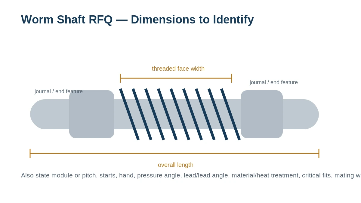
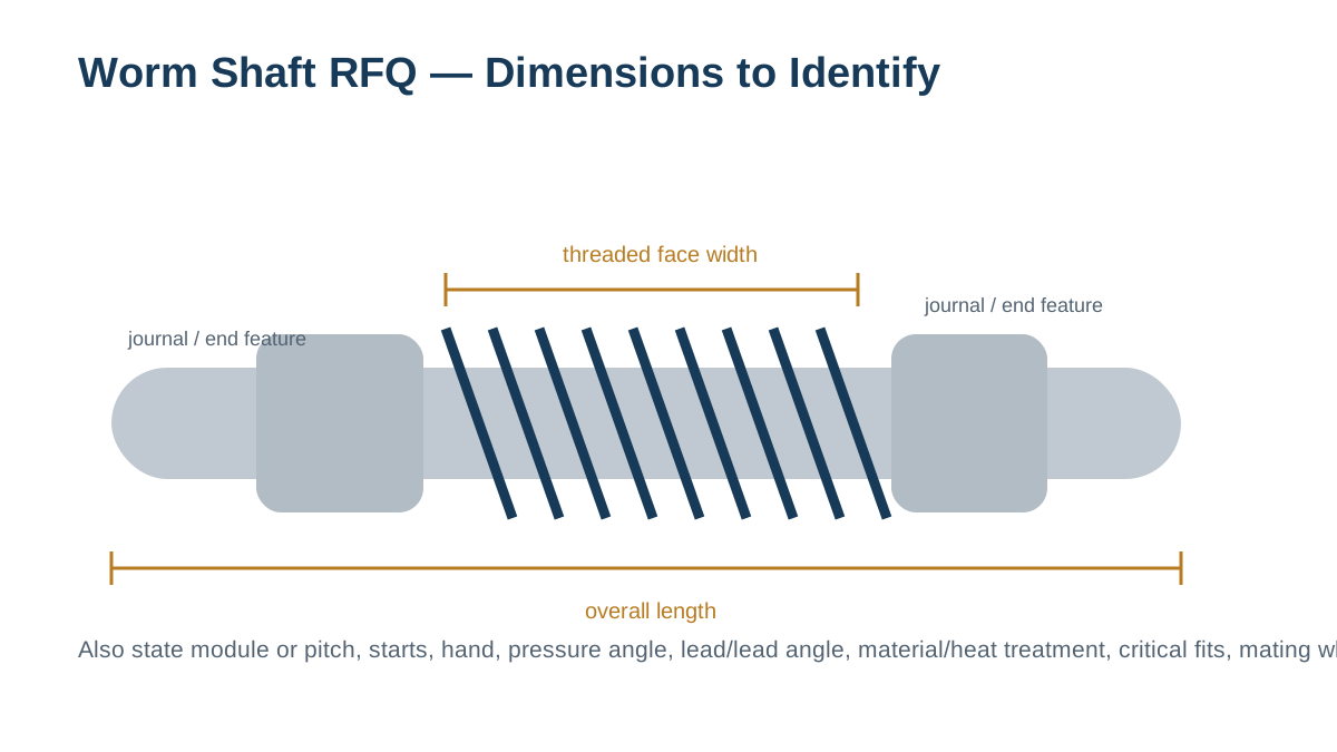
| Shaft interfaces | Overall length, threaded face width, bearing journals, shoulders, keyway/spline/thread/bore details and fit/tolerance notes. |
| Duty | Input speed, torque/load context, duty cycle, lubrication, temperature/contamination/corrosion conditions. |
| Production | Quantity, sample requirement, material/heat treatment, finish, inspection documentation and requested delivery. |
Send dimensions in one view when a full drawing is not available
A marked-up photo or sketch that identifies the overall length, threaded face, journals and end features is much more useful than a part name alone. Add the tooth data and mating-wheel information separately.
Gamme de produits
Choisissez l'arbre à vis sans fin en fonction du procédé de fabrication et des exigences d'entraînement.
Commencez par la fonction que vous devez contrôler. La géométrie est finalisée en fonction de la roue d'accouplement, des interfaces d'arbre et du mode de fonctionnement.
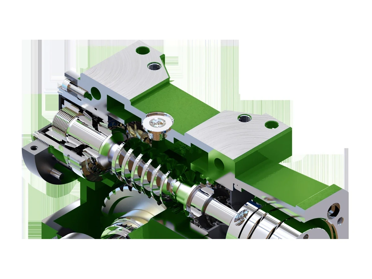
Finished flank route
Puits de vers de terre
Choose this path when the print calls for controlled finished worm flanks, post-treatment finishing or a grinding-specific inspection requirement.

Generated geometry
Arbres à vis sans fin taillés
A production-focused route for suitable geometry, material condition and duty, always confirmed against the drawing and mating wheel.
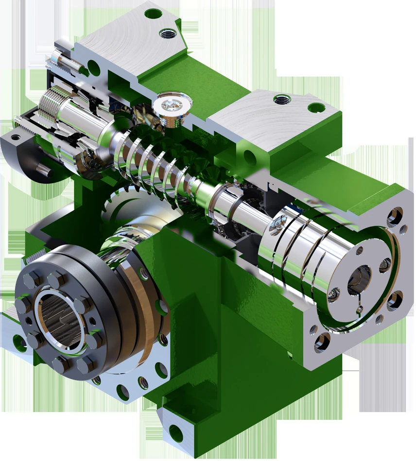
Axial mesh adjustment
Arbres à vis sans fin à double entrée
For drives designed to use axial worm movement as part of backlash setting, including the documented JDLB 45–90 family context.
One-start geometry
Arbres à vis sans fin à démarrage unique
For existing or new designs whose ratio and mating wheel are built around a single-start worm.
Lead and motion
Arbres à vis sans fin à démarrage multiple
For designs where the selected ratio, lead angle and speed relationship call for multiple starts.
Environment-led material
Stainless Steel Worm Shafts
For corrosion-sensitive projects where grade, strength, wear and mating material must be reviewed together.
Choose the product family by the decision you actually need to make
| Buyer situation | Best starting path |
|---|---|
| Replacement with known drawing | Use the matching manufacturing/configuration family, then quote directly from the current drawing revision and quantity. |
| Replacement with unknown tooth data | Start from the sample and mating wheel. Record ratio, center distance and machine reference before assuming module, pitch or lead. |
| New precision or adjustable drive | Review worm and wheel together. If axial backlash adjustment is part of the design, use the dual-lead family as the starting point. |
| New general industrial drive | Compare single-start, multi-start, generated and ground routes only after ratio, speed, load, duty and lubrication are defined. |
| Corrosive / washdown environment | Use the stainless category as a material discussion, then confirm the exact grade, treatment, wheel pairing and lubrication. |
| Pair-level contact or wear problem | Use the matched set category so worm and wheel condition, material and contact can be reviewed in one scope. |
Drawing control
From catalogue family to manufacturable shaft
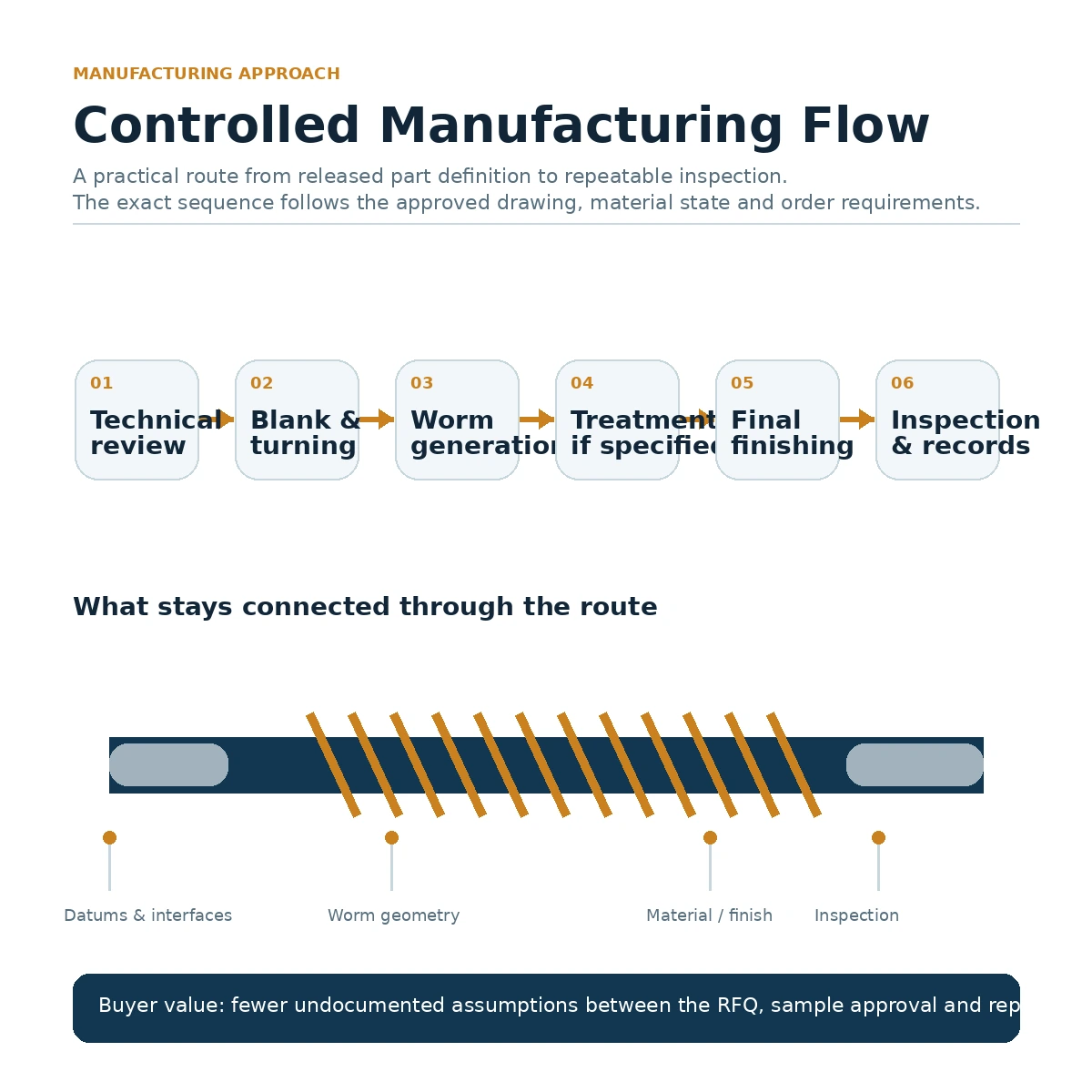
The website groups parts by useful buying logic, but the released component still needs one controlled definition. The worm geometry, journals, shoulders and end features must refer to the same drawing revision so the gear member and the supported shaft cannot drift apart.
When a buyer sends only a model name, the quotation normally remains conditional until the mating wheel or dimensional definition closes the missing interfaces. That is deliberate: an accurate quotation is more useful than a fast guess that cannot be manufactured safely.
What every detailed product page is designed to answer

Mesh definition
How starts, hand, module or pitch, lead data and the mating wheel define the transmitting geometry.
Shaft interfaces
Which journals, shoulders, keyways, splines, threads, bores and overall lengths must be supplied by the drawing.

Manufacturing route
Whether the part is generated, ground or otherwise finished, and which material/treatment inputs control that route.

Inspection scope
Which dimensions or gear characteristics must be checked and documented for the order.

Application duty
How speed, load, reversals, environment and lubrication affect what must be confirmed before production.

Order planning
How samples, mixed-model orders, delivery basis and destination are handled after the technical scope is stable.
Citation tirée des interfaces réelles
Demande de devis / Envoyer une demande de prix
Veuillez fournir la référence du modèle ou du dessin, la quantité, l'application et la géométrie qui détermine l'ajustement et le maillage. Les valeurs inconnues peuvent être identifiées pour confirmation plutôt que d'être devinées.
























