Application
Worm Shafts for Packaging & Conveying Equipment
Packaging and conveying machinery often values compact motion, predictable adjustment and straightforward replacement.

Buyer decision
What changes the worm shaft specification here
The useful starting point is the operating duty, not a generic industry label. For this application, put extra attention on cycle rate, input speed, ratio, back-driving requirement, washdown/corrosion exposure, space and maintenance access.
For packaging & conveying equipment, review those inputs together with the mating worm wheel, center distance and shaft interfaces. The approved drawing remains the controlling reference for manufactured geometry.

Application RFQ checklist
| Input | What to provide |
|---|---|
| Cycle rate | State the actual value, condition or drawing reference for this project. |
| Input speed | State the actual value, condition or drawing reference for this project. |
| Ratio | State the actual value, condition or drawing reference for this project. |
| Back-driving requirement | State the actual value, condition or drawing reference for this project. |
| Washdown/corrosion exposure | State the actual value, condition or drawing reference for this project. |
| Space and maintenance access | State the actual value, condition or drawing reference for this project. |
Product paths commonly considered
Single/multi-start, stainless or custom ground/hobbed configurations depending on the machine. The final route depends on the complete mesh geometry, ordered material/treatment and inspection requirement.
For a packaging & conveying equipment repair, include the old shaft and wheel together when the tooth data cannot be recovered reliably from the machine documentation.
How we move from application to part
Define the machine duty
Record the operating condition and failure/selection objective.
Identify the mesh
Confirm the mating wheel, ratio, center distance and known tooth data.
Lock shaft interfaces
Journals, shoulders, end features and mounting constraints come from the approved print or measured sample.
Choose a manufacturing route
Hobbing, grinding and treatment are selected for the actual specification, not as marketing defaults.
Quote and confirm
Quantity, documentation and delivery are agreed before production.
Frequently asked questions
Can you select a worm shaft from the application name alone?
No. Application context helps us ask the right questions, but the worm/wheel geometry and shaft interfaces still need to be defined.
Should I send the mating worm wheel?
Yes when replacing an unknown shaft or when backlash/contact is a concern. A matched review is safer than assuming a standard mesh.
Can you make a small sample quantity?
For packaging & conveying equipment, 1–5 samples can be considered where the manufacturing route is suitable. A 1–2 piece order is also possible, normally at a higher unit cost.
Application detail
Cycle rate and downtime can be as important as nominal torque
Packaging and conveying equipment often combines repeated cycling, frequent changeover and compact adjustment mechanisms. The shaft may be a power-transmission member, a position-setting mechanism or part of a line of linked worm units; each case needs a different replacement record.
Record the machine station, direction of motion, cycle rate and adjustment function before removing the part. If several stations share a line shaft, quote the coupled arrangement and center distances so one local replacement does not introduce a new alignment problem.
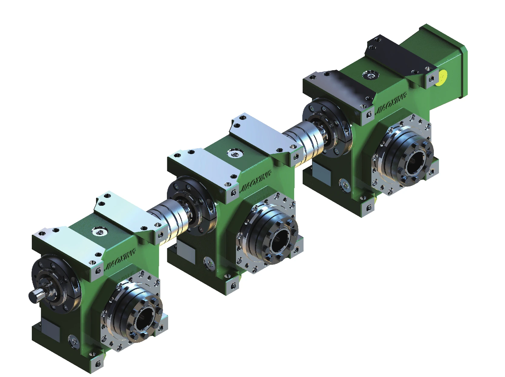
What to record before the RFQ leaves your plant
| Field | Why it matters |
|---|---|
| Machine function | Power transmission, adjustment, indexing, lift or positioning. |
| Cycle pattern | Continuous running, intermittent cycles, reversals and changeover frequency. |
| Environment | Cleaning method, moisture/product exposure and lubricant constraints. |
| Linked stations | Number of worm units, center distances and coupling/line-shaft arrangement. |
| Downtime target | Spare requirement, planned maintenance window and repeat-order identification. |
Useful product routes from this application
Packaging and conveying machines may use a ground, generated or dual-lead component depending on whether the station is transmitting power, positioning or adjusting. Use the catalogue to choose that family only after the station function is identified.
If several stations share a worm-shaft line, include the coupled layout and center distances in the RFQ. The selection guide can then be used to close the geometry and duty information for each controlled component.
Quote from the real interfaces
Request a Quote / Send RFQ
Send the model or drawing reference, quantity, application and the geometry that controls fit and mesh. Unknown values can be identified for confirmation rather than guessed.
























