Application-first selection
Worm Shaft Applications
A worm shaft works as part of a mesh and a machine. The application changes which inputs matter most: positioning accuracy, load, environment, lubrication, replacement access or compact layout.
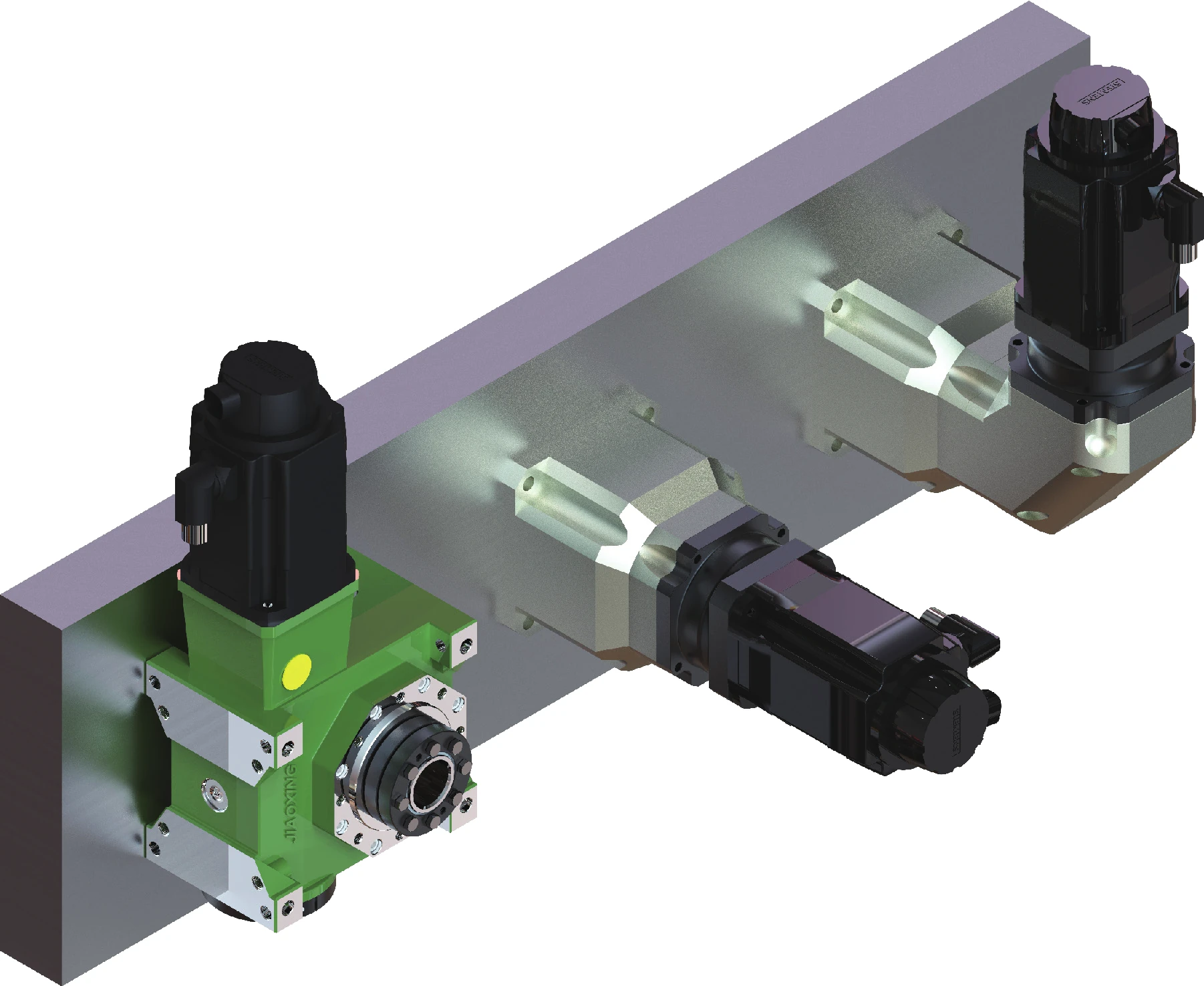
Start with the machine task, then confirm the shaft
Application pages do not assign one material or one tolerance to an entire industry. They show the questions that change the specification. A robot indexing axis and a heavy-duty reducer may both use a worm, but the quote inputs are not the same.
Explore by application

Industrial Automation & Reducers
Reducer inputs, adjustment drives and compact right-angle power transmission.

Robot Joints & Precision Indexing
Indexing and controlled rotary mechanisms where mesh adjustment and repeatability matter.

Automotive Transmission Mechanisms
Print-to-spec worm shaft components for vehicle and mobility mechanisms.

Aerospace Actuation Projects
Drawing-controlled components with project-defined inspection and documentation requirements.

Heavy Machinery Drives
Load, wear, lubrication and maintainability-led worm shaft selection.

Packaging & Conveying Equipment
Compact drive, adjustment and positioning functions in handling machinery.
System context
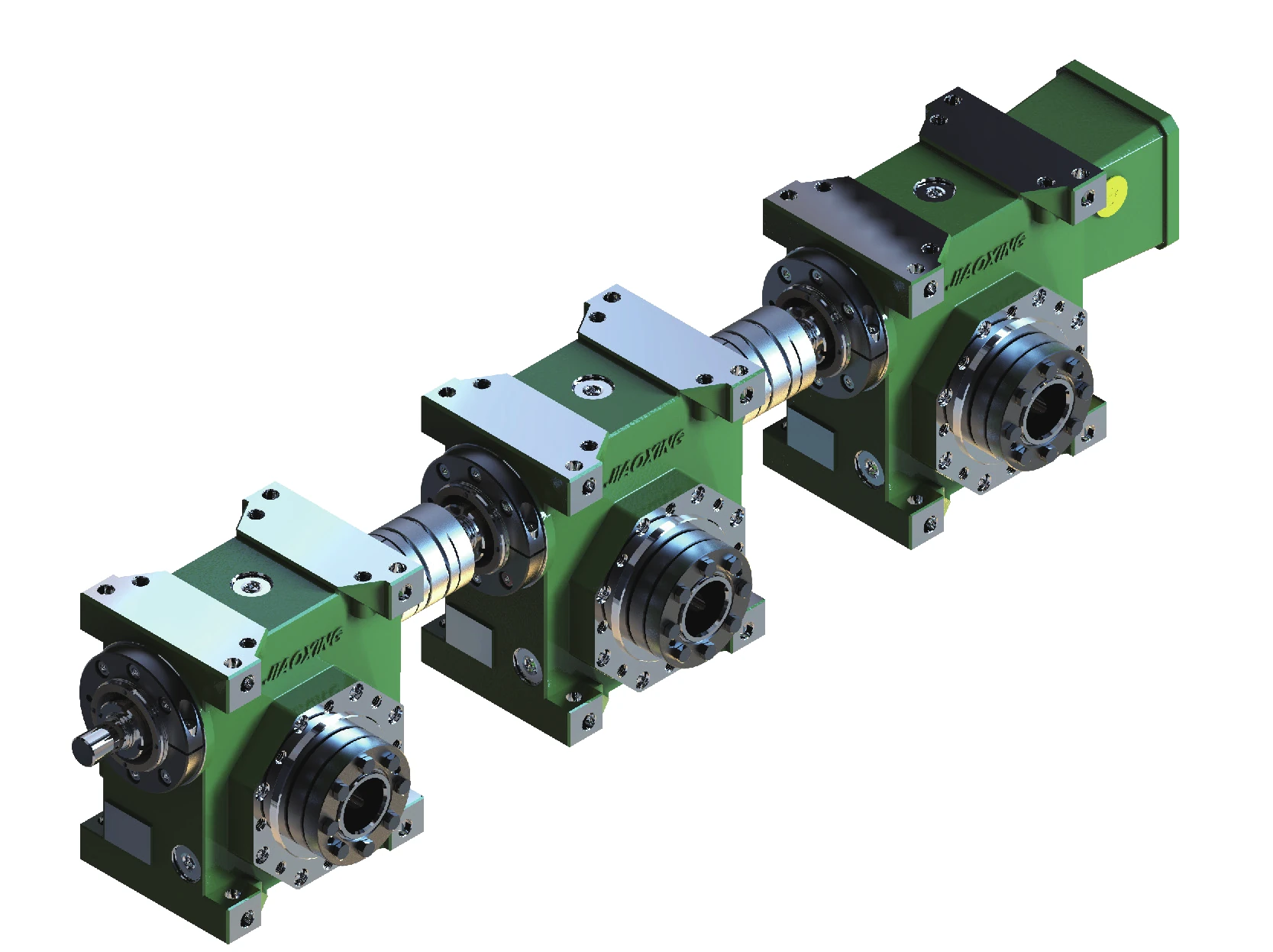
Multiple worm wheels can be coordinated from a common shaft line
The JDLB series context includes layouts where worm shafts are driven in series to support synchronous output across multiple worm-wheel units. If your machine uses a linked arrangement, provide the center distances, coupling method, motor/input information and required synchronization or positioning behavior.
A linked arrangement magnifies alignment and torsional effects. Quote the system interfaces, not only one isolated shaft diameter.
Open the application guide that matches the machine task
Each guide uses different selection questions instead of repeating one generic worm-shaft page.
Positioning & compact drives
Industrial Automation & Reducers
Review backlash/positioning target, ratio, speed, duty cycle, bearing support and coupling layout.
Reversing motion
Robot Joints & Precision Indexing
Lost motion, repeatability, direction reversals and adjustment strategy often deserve more attention than nominal shaft diameter.
Drawing-controlled programs
Automotive Transmission Mechanisms
Material/treatment, interface fits and the validation plan need to be fixed before the manufacturing route is finalized.
Specification-led work
Aerospace Actuation Projects
Drawing revision, process requirements, traceability and ordered inspection scope have to be explicit; qualification is never assumed.
Load & wear
Heavy Machinery Drives
Shock, contamination, lubrication, service access and wear evidence guide the replacement or new-part review.
Cycles & changeover
Packaging & Conveying Equipment
Cycle rate, reversals, sanitation/environment, adjustment frequency and downtime constraints help define the useful part data.
Application question → technical implication
| Machine condition | What it changes in the RFQ |
|---|---|
| Frequent reversals or indexing | Check the lost-motion/backlash requirement, shaft support and adjustment method rather than quoting only the nominal ratio. |
| High load or shock | State the load/torque context, duty cycle, bearing arrangement, material/treatment requirement and lubrication condition. |
| Corrosive or washdown environment | Define environment, exact material grade or restriction, mating material and lubricant compatibility. |
| Difficult replacement access | Treat interchange dimensions, datum locations, service procedure and repeat-order identification as critical characteristics. |
| Multiple linked worm units | Provide center distances, shaft/coupling arrangement, torsional path and the synchronization expectation across the machine. |
| Prototype machine | Separate design assumptions from controlled dimensions and identify what must be proven before repeat production. |
The application becomes useful only when it is translated into part data
The machine task narrows the questions; it does not replace the drawing. Use the application context to identify the speed, load, environment, adjustment and maintenance conditions that the shaft and worm-wheel pair must survive, then control the actual geometry in the part definition.
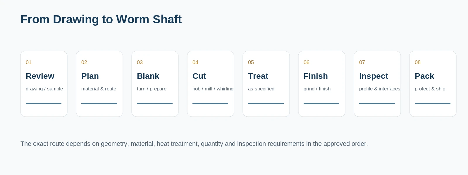
Quote from the real interfaces
Request a Quote / Send RFQ
Send the model or drawing reference, quantity, application and the geometry that controls fit and mesh. Unknown values can be identified for confirmation rather than guessed.
























