Manufacturing
Worm Shaft Manufacturing Process
The correct route depends on the worm geometry, material condition, treatment, finish requirement, quantity and the interfaces that must remain concentric with the threaded section.
Planning
Start from the controlling geometry
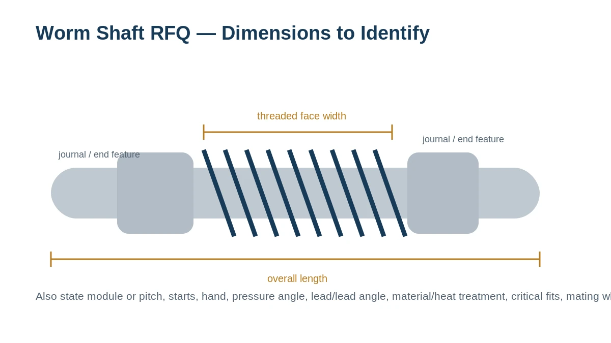
Before metal is cut, the drawing or measured sample has to define the worm and the shaft as one part. Module or pitch, pressure angle, starts, hand, lead/lead angle and threaded face are reviewed together with bearing journals, shoulders and end features.
For an unknown replacement, the mating worm wheel and center distance help prevent an apparently similar worm from producing the wrong contact or ratio.
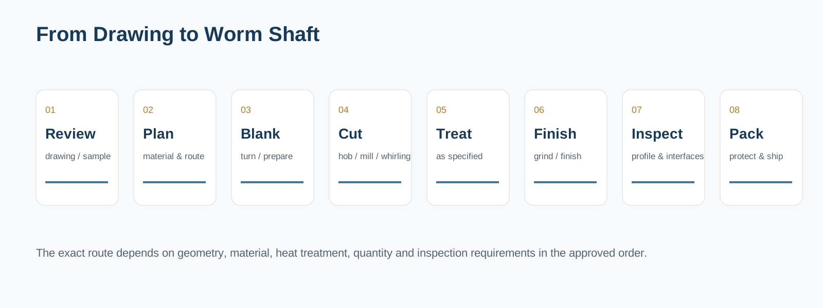
Typical manufacturing route
Technical review
Confirm drawing revision, material, quantity, tooth data, critical interfaces and inspection scope.
Material and blank
Procure the specified material and prepare the blank with allowance for later tooth and journal operations.
Turning / reference surfaces
Create datums, centers, journals and shoulders in the sequence required by the part plan.
Worm generation
Use the selected cutting route—such as hobbing, milling or whirling—when it fits the geometry and material state.
Heat treatment
Apply only the treatment specified or approved for the ordered part; account for resulting distortion and finishing needs.
Grinding / finishing
Finish the worm thread or critical journals where the drawing and process plan require it.
Inspection
Check the dimensions and tooth/profile/contact attributes defined by the order and inspection plan.
Protection / packing
Clean, protect critical surfaces and pack the component for the agreed shipping method.
The route is a sequence of controlled decisions
A ground worm shaft is not simply a hobbed shaft with an extra marketing label. Grinding is positioned in the route to achieve the ordered finished geometry after the preceding operations. Likewise, heat treatment is selected around the specified material and service requirement—not applied as a one-size-fits-all claim.
Manufacturing route variables to confirm
| Parameter | Specification / guidance |
|---|---|
| Blank and datums | Overall geometry, center holes, reference faces and machining allowances. |
| Worm generation | Profile definition, module/pitch, starts, hand, lead/lead angle, face width and cutting route. |
| Heat treatment | Material-specific requirement, hardness/depth if specified, distortion allowance and post-treatment finishing. |
| Grinding / finish | Thread/journal surfaces that require finishing and any surface or geometry requirement on the drawing. |
| End features | Keyways, splines, threads, bores, flats, cross holes or other interfaces. |
| Inspection | Dimensional report, material document, hardness check, gear measurement or contact verification as ordered. |
Capabilities are quoted to the drawing, not assumed from a generic range
Worm-shaft capability is reviewed from the actual geometry, material condition, treatment sequence, quantity and inspection requirement. Machine limits, grinding class and special-process requirements are confirmed for the specific RFQ rather than presented as one universal range.
If your RFQ needs a specific machine process, grinding class, inspection method or special-process approval, state it on the enquiry so it can be confirmed before quotation.
Frequently asked questions
Do all worm shafts need grinding?
No. The manufacturing route depends on the required geometry, material/treatment, accuracy, finish, quantity and application. Some parts are suitable for a generated/hobbed route; others require grinding.
Can you manufacture from a sample?
Yes for replacement evaluation. A sample is more useful when it is sent with the mating wheel, center distance and operating context, especially if the tooth data are not documented.
Can I specify my own material and heat treatment?
Yes. Put the material grade, treatment and required hardness/depth or standard directly on the drawing or RFQ. We do not replace those requirements with a generic website value.
Quote from the real interfaces
Request a Quote / Send RFQ
Send the model or drawing reference, quantity, application and the geometry that controls fit and mesh. Unknown values can be identified for confirmation rather than guessed.
























