
Beschrijving
Product definition
Define this product before manufacturing
A hobbed/generated route is reviewed around module or pitch, starts, hand, lead, blank condition and quantity. Heat treatment and any later finishing operation must be compatible with the required final geometry.
For custom hobbed worm shaft, the RFQ should connect tooth geometry to bearing journals, shoulders and the input/output interface. Unknown values can be marked for technical review rather than replaced with generic website dimensions.
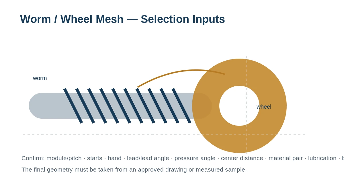
Technical specification table
| Parameter | Specification / guidance |
|---|---|
| Module / diametral pitch | Drawing / RFQ required |
| Starts | Drawing / RFQ required |
| Hand | Right / left as specified |
| Pressure angle / profile | Drawing / RFQ required |
| Lead / lead angle | Drawing / RFQ required |
| Threaded face width | Drawing / RFQ required |
| Overall length | Drawing / RFQ required |
| Bearing journals / fits | Drawing / RFQ required |
| End features | Keyway / spline / thread / bore / flat / other as specified |
| Material | Buyer specification or application-reviewed selection |
| Heat treatment / hardness | Per approved specification; not assumed |
| Surface / finish requirement | Per drawing and selected manufacturing route |
| Mating worm wheel | Supply tooth count, material, center distance / drawing where available |
| Quantity | Prototype, 1–5 sample where suitable, or production quantity |
| Inspection / documents | Define required report/material/treatment/gear checks in RFQ |
RFQ geometry for Custom Hobbed Worm Shaft
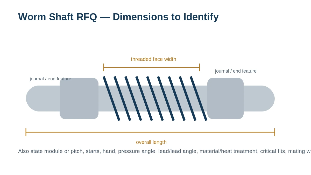
For custom hobbed worm shaft, put the worm thread and shaft interfaces on the same controlled sketch or drawing. Concentricity, shoulder locations and end features can influence how the part sits in the bearings and therefore how the mesh behaves.
Where this configuration is considered
Typical enquiries include industrial reducers, conveyors, adjustment mechanisms and production programs where generated tooth geometry satisfies the ordered requirement. The application sets the duty and documentation context, while the approved drawing or project specification sets the actual part geometry.
Order path for Custom Hobbed Worm Shaft
Send part definition
Provide the drawing/sample, mating-wheel context, quantity and application.
Close technical gaps
Review the unknown items that are specific to custom hobbed worm shaft before the quotation is finalized.
Confirm commercial scope
Agree quantity, delivery basis and required documents.
Manufacture
Run the approved material/process route for the controlled part definition.
Inspect and release
Check the characteristics defined by the order before packing and shipment.
Veelgestelde vragen
Can custom hobbed worm shaft be reverse-engineered from a worn sample?
A sample can establish interfaces and approximate tooth data, but the mating wheel or machine ratio helps confirm whether the observed form is the intended generated geometry.
How should the manufacturing route be specified for custom hobbed worm shaft?
If the process itself is not controlled, provide the required finished tooth geometry and inspection criteria so the manufacturing route can be selected appropriately.
Should the mating worm wheel be included with a custom hobbed worm shaft RFQ?
Include the wheel drawing or sample when ratio, contact, wear or backlash is uncertain. For custom hobbed worm shaft, the mating member is often the fastest way to prevent an incorrect tooth interpretation.
Configuration detail
Use hobbing or another generating route only where the finished requirement supports it
A generated worm shaft can be a practical production solution, but the process decision follows the material state, geometry, finish, quantity and inspection requirement. If a later treatment or finishing step changes the final geometry, that sequence belongs in the approved process plan.
For a custom hobbed or generated shaft, use the RFQ to distinguish finished requirements from process preference. The controlled definition should show the geometry and interfaces; the manufacturing plan can then determine when generation, treatment and any later finishing steps occur.

Points to close before manufacturing release
| Control point | What to define |
|---|---|
| Geometrie | Module/pitch, starts, hand, profile and lead data. |
| Material state | Condition before and after worm generation. |
| Finish requirement | What the generated surface must achieve in the final part. |
| Quantity | Prototype and repeat volume expected for process planning. |
From dimensional definition to controlled production
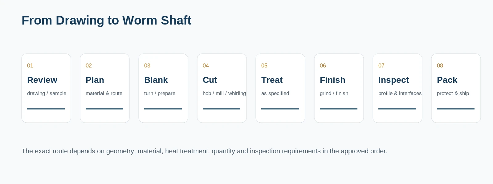
Production becomes repeatable when the material state, generation stage and final inspection are connected to one released part definition. If a customer mandates a particular process or record, reference that requirement directly on the order or controlled specification.
Citaat uit de echte interfaces
Offerte aanvragen / Offerteaanvraag versturen
Stuur het model of de tekeningreferentie, de hoeveelheid, de toepassing en de geometrie die de pasvorm en de maaswijdte bepaalt. Onbekende waarden kunnen worden geïdentificeerd ter bevestiging in plaats van te worden gegokt.
























