EVER POWER · worm shaft supply
Precision Worm Shafts for Industrial Power Transmission
Custom and series-based worm shafts for reducers, automation, indexing, robotics and replacement programs. Send a drawing, a mating worm wheel specification or a sample; we will work from the interfaces that matter instead of forcing your project into a generic size chart.



Product range
Choose the worm shaft by manufacturing route and drive requirement
Start with the function you need to control. Geometry is finalized against the mating wheel, shaft interfaces and operating duty.
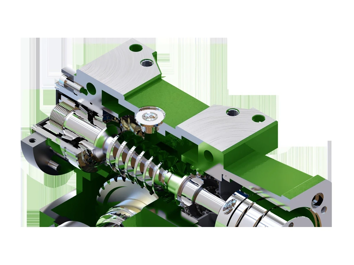
Finished tooth surface
Grondwormschachten
For applications that call for thread grinding after the preceding machining and treatment route.

Efficient generation
Tandwielassen
A practical route for suitable geometry, material condition, quantity and duty.
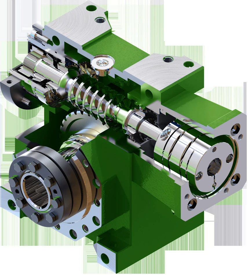
Adjustable mesh
Wormasten met dubbele geleiding
JDLB 45–90 component families plus custom dual-lead requirements.
Ratio-led selection
Single-Start Worm Shafts
One-start geometry coordinated with the tooth count and geometry of the mating wheel.
Lead and speed
Multi-Start Worm Shafts
Multiple starts for drive designs that require a different lead, ratio or operating behavior.
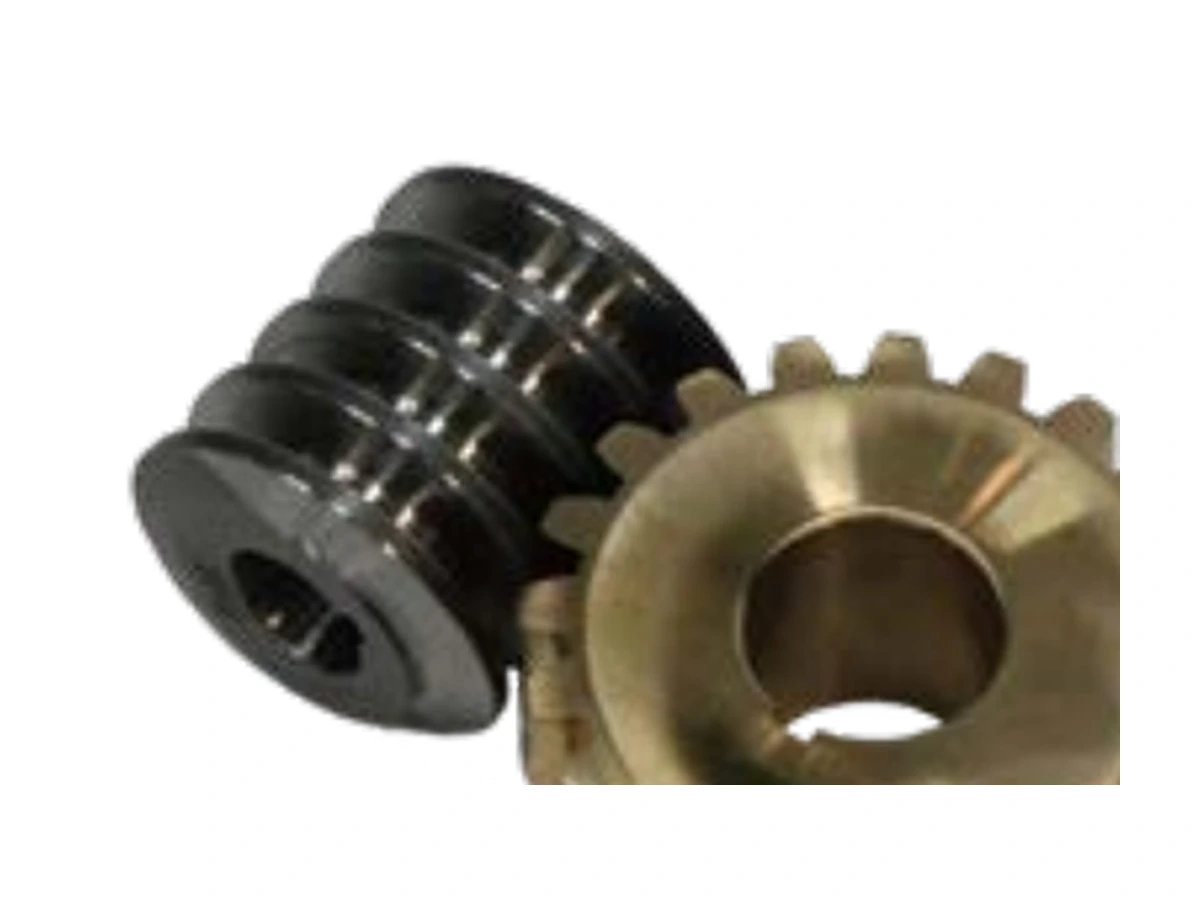
Pair-level control
Matched Worm / Wheel Sets
Useful when contact, backlash and material pairing need to be reviewed together.
Selection logic
A worm shaft is not selected by diameter alone
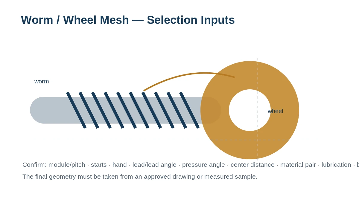
The threaded geometry and the shaft interfaces have to agree with the mating wheel, center distance, hand, start count and the operating duty. Bearing journals, keyways, splines and shoulders can be just as critical as the worm thread itself.
For replacement work, a usable quotation can start from a drawing, an existing model reference, a worn sample or clear measurement photos. For a new design, give us the intended ratio, input speed, load/torque context, lubrication and any backlash or positioning requirement.
Where the worm shaft is used

Reducers and industrial machinery
Right-angle transmission, speed reduction and compact drive layouts where the worm meshes with a dedicated worm wheel.

Automation and indexing
Rotary/indexing mechanisms and controlled positioning systems that need a defined mesh, shaft interface and repeatable adjustment procedure.

Vehicle mechanisms
Custom transmission, actuator and auxiliary drive components made to an approved part specification rather than generic interchange claims.

Actuation projects
Component manufacturing for controlled actuation projects when the buyer provides the required drawing, inspection and documentation scope.

Heavy machinery
Worm-shaft components for industrial equipment where load, wear, lubrication and replacement accessibility shape the specification.

Packaging and conveying
Compact motion and adjustment mechanisms used in packaging, handling and conveyor equipment.
Dual-lead worm shafts: adjustment happens in the assembled mesh
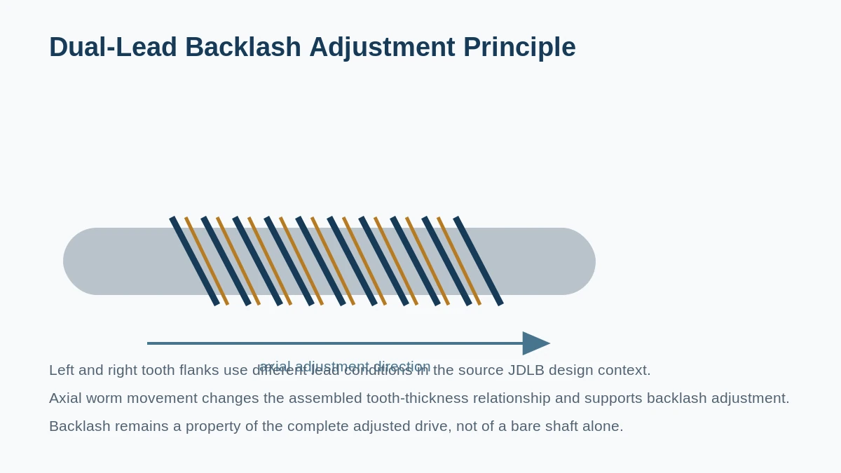
In the JDLB drive family, the left and right tooth flanks use different lead conditions. Axial movement of the worm changes the tooth-thickness relationship in the mesh, giving the assembly a way to set backlash. This is a system behavior: the target cannot be guaranteed by quoting a bare shaft without the mating wheel and adjustment context.
Series-based supply
JDLB 45–90 component context
The JDLB high-precision worm-drive range covers six principal sizes: 45, 50, 55, 63, 75 and 90. Dual-lead worm geometry is used so the assembled mesh can be adjusted axially, while the number of worm starts changes with the ratio configuration.
For replacement or component supply, identify the JDLB size and ratio, then provide the current shaft or drawing whenever possible. End features, material, treatment and inspection scope are confirmed for the ordered configuration.
A practical print-to-spec workflow
Review the part
We check the drawing, sample or drive reference and identify the interfaces that control fit and mesh.
Confirm the route
Material, blank preparation, worm-cutting route, heat treatment and finish operations are aligned to the ordered requirement.
Control the mesh geometry
Module or pitch, starts, hand, lead/lead angle and mating-wheel information are reviewed together.
Finish critical interfaces
Bearing journals, shoulders, keyways, splines, threads and other end features follow the approved drawing.
Inspect what the order defines
Dimensional checks and gear-profile/contact verification are planned around the specification and requested documentation.
Protect for shipment
Finished components are cleaned, protected and packed for the destination and order format.
Ordering
Commercial terms for prototype and mixed orders
Frequently asked questions
What information should I send for a worm shaft quotation?
A drawing is best. If it is not available, send the existing part or clear photos and measurements, plus the mating worm wheel or reducer reference, quantity, application, input speed/load context and any known module, pitch, starts, hand or center distance.
Can you quote only the worm shaft without the worm wheel?
Yes when the required geometry is clearly defined. For a replacement with unknown tooth data, supplying the mating wheel information or sample greatly reduces the risk of an incorrect mesh.
What is the difference between single-start and multi-start worms?
The number of starts changes lead and the relationship between worm turns and wheel movement. It also influences lead angle and drive behavior. The correct choice belongs to the complete worm/wheel design rather than a keyword label.
Does a worm drive always self-lock?
No. Back-driving behavior depends on lead angle, friction, lubrication, temperature and load. Safety functions should never rely on a general self-locking assumption without application-specific evaluation.
Can you handle JDLB replacement components?
The available material identifies JDLB 45, 50, 55, 63, 75 and 90 dual-lead drive families. Send the size, ratio and current part/drawing so the component-level geometry and interfaces can be confirmed.
Can small quantities be ordered?
Yes. One or two pieces can be considered, usually at a higher unit cost. Where the route is suitable, new buyers may request 1–5 samples before a larger program.
Quote from the real interfaces
Request a Quote / Send RFQ
Send the model or drawing reference, quantity, application and the geometry that controls fit and mesh. Unknown values can be identified for confirmation rather than guessed.
























