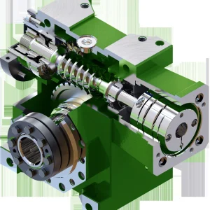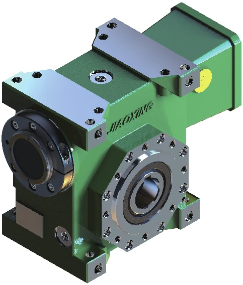
Description
Size-specific context
Where JDLB 63 sits in the range
JDLB 63 is the mid-range JDLB size where the documented adjustment distance rises to 10 mm and the output load figures step up materially from sizes 45–55. The dual-lead principle lets the assembled mesh be adjusted by moving the worm axially; it does not make the bare shaft interchangeable with another family size.
For JDLB 63, include the housing/bearing context when the old unit shows uneven flank wear. Higher documented radial and axial load capability does not remove the need to preserve alignment and center distance.
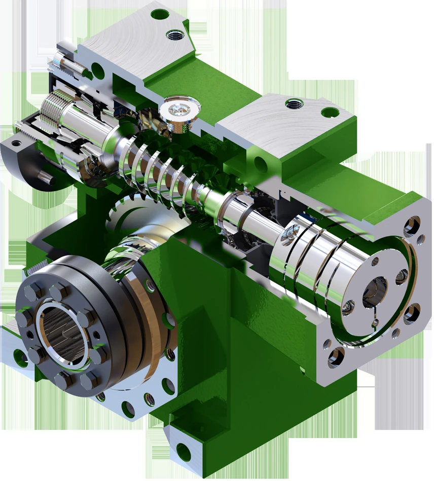
JDLB 63 size and adjustment data
| Parameter | Specification / guidance |
|---|---|
| Series size | JDLB 63 |
| Drive concept | Dual-lead worm drive with axial backlash adjustment |
| Documented ratio contexts | 14.5, 19.5, 24.5*, 30, 40*, 45, 50*, 60, 90 |
| Lead-angle examples | 12°50′ at 14.5; 10°29′ at 19.5; 6°30′ at 30; 4°48′ at 45; 3°47′ at 60; 2°40′ at 90 |
| Adjustment distance V | 10 mm |
| Adjustment coefficient k | 0.025–0.05 mm⁻¹ |
| Clearance adjustment ΔSd | 0.25–0.50 mm |
| Input shaft diameter J | 20 mm |
| Envelope A / B / C | 134 / 173 / 66 mm |
| Drive-level P0 grade | 2 arc minutes |
| Drive-level P1 grade | 3–5 arc minutes |
| Documented output radial load Fr2 | 8400 N |
| Documented output axial load Fa2 | 8100 N |
| Material / heat treatment of replacement shaft | Confirm from ordered drawing or approved project specification |
Selected JDLB 63 performance references
| Ratio context | Documented performance reference |
|---|---|
| Ratio 14.5 | At n1=1400 min⁻¹: dynamic efficiency 0.82; rated input power 1.7 kW; output torque 140 Nm; output speed 96.6 min⁻¹. |
| Ratio 45 | At n1=1400 min⁻¹: dynamic efficiency 0.67; rated input power 0.8 kW; output torque 140 Nm; output speed 31.1 min⁻¹. |
| Ratio 90 | At n1=1400 min⁻¹: dynamic efficiency 0.53; rated input power 0.4 kW; output torque 120 Nm; output speed 15.6 min⁻¹. |
Adjustment data for JDLB 63
The documented adjustment range for size 63 uses V=10 mm, k=0.025–0.05 mm⁻¹ and ΔSd=0.25–0.50 mm. These values describe the reducer adjustment context and should not be converted into a standalone tooth tolerance on a replacement shaft.
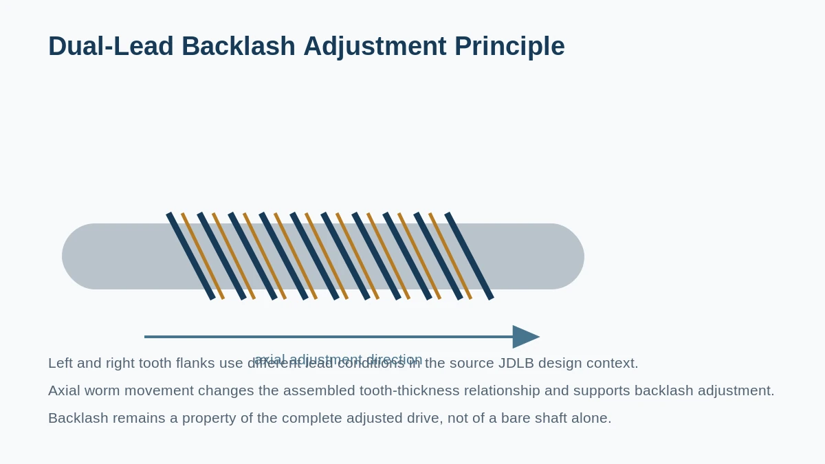
Ratio, starts and replacement identification
The size-63 mesh table spans these documented ratio contexts: 14.5, 19.5, 24.5*, 30, 40*, 45, 50*, 60, 90. Worm start count and lead angle change with the selected ratio, so the reducer size alone is not enough to manufacture a replacement worm.
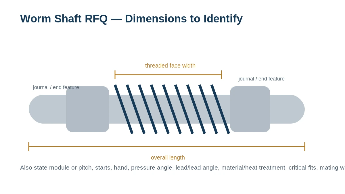
When the old shaft is worn, read the ratio plate or gearbox record and inspect the mating wheel before finalizing tooth geometry. For JDLB 63, also include the shaft end interfaces and bearing-journal dimensions in the same RFQ.
Replacement RFQ
What to send for a JDLB 63 quote
Send the size-63 reducer reference, ratio, quantity, current worm-shaft drawing or measured sample, and the mating-wheel condition. Mark any surfaces affected by wear so measured damage is not treated as intended geometry.
For JDLB 63, the order review should reflect that the mid-range JDLB size where the documented adjustment distance rises to 10 mm and the output load figures step up materially from sizes 45–55. State the requested 2 arc minutes P0 or 3–5 arc minutes P1 drive grade as an assembled-mesh target and include the wheel condition plus the documented V=10 mm adjustment context.
Frequently asked questions
What changes at JDLB 63 compared with the smaller sizes?
The documented size data move to a 10 mm adjustment distance, 20 mm input-shaft diameter and higher output radial/axial load figures than the 45–55 group.
Can JDLB 63 be ordered from the size number alone?
No. The 63 family still contains different ratio/start/lead conditions. Send the ratio and current shaft or wheel data so the tooth relationship can be confirmed.
What if the JDLB 63 wheel is also worn?
Quote the size-63 worm and wheel together when wear or contact condition makes the original mesh uncertain. Pair-level review avoids treating a damaged mating member as a valid reference.
Replacement / service
Use JDLB 63 as a drive-family reference, then confirm the actual shaft
The JDLB 63 page carries documented series context for a dual-lead worm drive, including size-specific envelope, adjustment and selected drive-performance references already shown above. Those figures describe the drive family; they do not define every bearing journal, end feature or replacement shaft dimension.
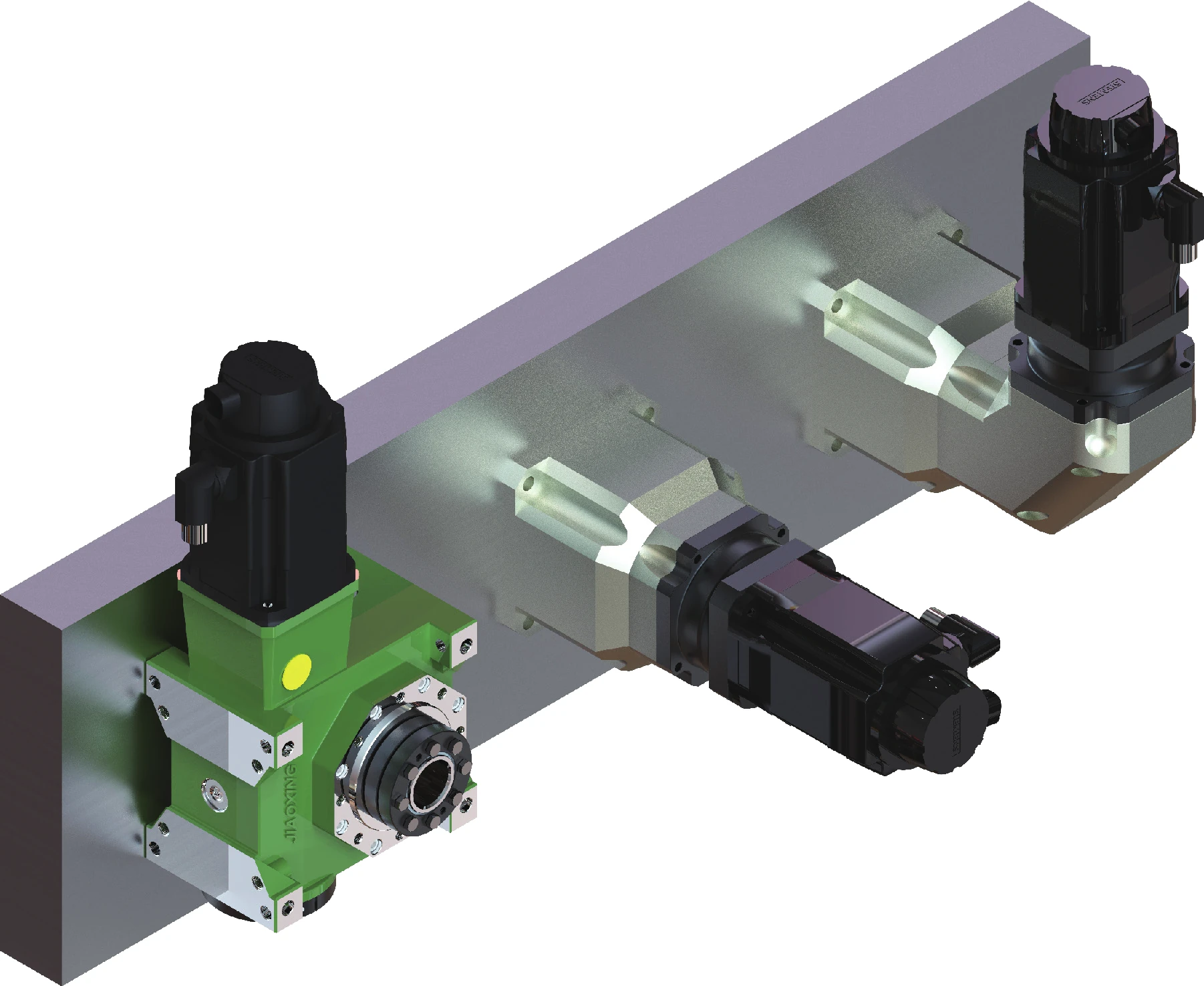
On JDLB 63 replacements, preserve the reducer/ratio identity and note how the current shaft is axially located before disassembly. If the objective is backlash correction, check the wheel, bearings and housing relationship together with the worm.
JDLB 63 order-release checklist
| Release item | Information to supply |
|---|---|
| Drive identity | JDLB 63 size reference plus ratio / model information. |
| Existing shaft | Drawing, sample, or trusted dimensions for journals, shoulders and input/end interfaces. |
| Mating wheel | Current wheel condition and identifying data; include it when tooth geometry or contact is uncertain. |
| Adjustment state | Current axial adjustment/reference position and the reason for replacement or backlash correction. |
| Duty | Input speed, load/torque context, reversals and lubrication condition. |
| Inspection | State whether the order needs dimensional records, material/treatment evidence or pair/assembly checks. |
Where the JDLB 63 shaft sits in a multi-unit drive context
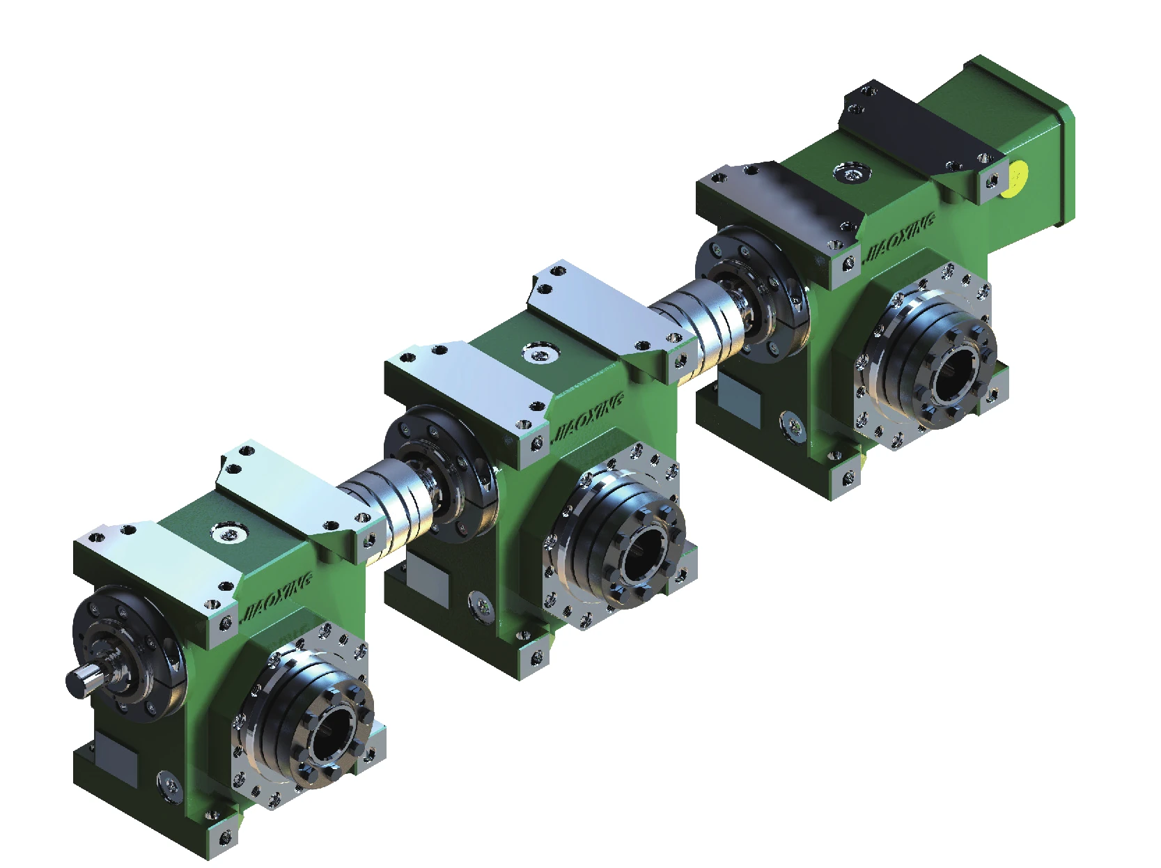
If a size-63 shaft transmits motion through more than one worm station, identify every coupled location that depends on the same line. This makes the replacement review about the whole locating path rather than only one machined segment.
Quote from the real interfaces
Request a Quote / Send RFQ
Send the model or drawing reference, quantity, application and the geometry that controls fit and mesh. Unknown values can be identified for confirmation rather than guessed.